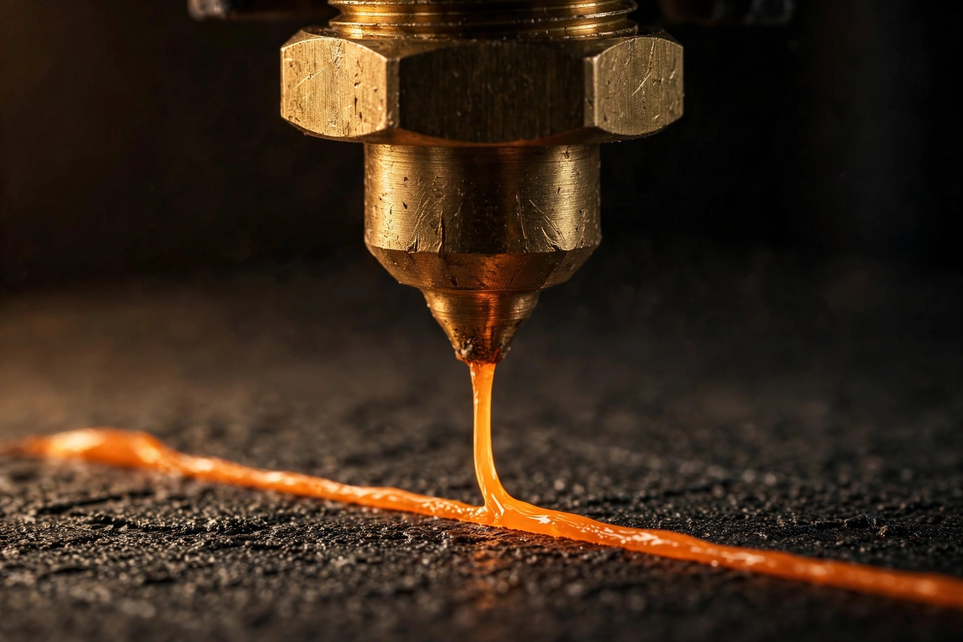
A slicer turns a 3D model into the layer-by-layer motion and extrusion instructions a printer follows. OrcaSlicer and FlashPrint present many controls, but a beginner only needs to understand a core group: machine profile, material profile, layer height, walls, infill, supports, temperature, speed, and plate placement. Everything else can stay at a tested default until a print gives you a reason to change it.
Choose the correct machine before touching settings
The printer profile defines build volume, origin, nozzle diameter, movement limits, and start and end routines. Select the exact printer and hardware revision when available. If you changed the nozzle, update its diameter in both the machine and print profile. A file sliced for a 0.4 mm nozzle will not behave correctly through a 0.6 mm nozzle simply because the machine can extrude it.
FlashPrint offers a guided path for supported Flashforge machines and is often the easiest place to establish a reliable baseline. OrcaSlicer exposes deeper calibration, arrangement, support, and multi-material tools. Neither is universally “better.” Start with the application that has a verified profile for your machine and lets you send files through a connection method you trust.
Import, orient, and inspect the model
Common mesh formats describe surface geometry, not material or guaranteed dimensions. After importing, verify size and units. Place the broadest sensible face on the bed, but consider strength and support as well as convenience. A functional hook may need to lie on its side so layers follow the curve instead of splitting across it.
Use the slicer's repair warning as a prompt to inspect non-manifold edges or inverted faces. Automatic repair can fix simple mesh issues, but it cannot know the designer's intent. If a thin wall vanishes in preview, the geometry may be narrower than the chosen line width or the feature may not be solid.
Layer height and line width
With a 0.4 mm nozzle, a 0.20 mm layer height is a sensible general starting point. Lower heights show finer vertical detail and shallower stair-stepping but increase print time. Higher layers print faster but reduce fine detail and can approach the nozzle's practical limit. The first layer is often thicker to improve tolerance of tiny bed variations.
Line width is related to, but not identical to, nozzle diameter. Tested profiles may use a slightly wider extrusion for strong, well-bonded walls. Avoid changing line width, flow, and nozzle size together. Preview whether narrow features receive one line, several lines, or disappear.
Walls, top layers, and infill
Wall loops form the outside shell and often contribute more useful strength than dense infill. Three walls are a good practical baseline for many parts; decorative models may need fewer, while loaded brackets may need more and should be tested. Top and bottom thickness should be judged in millimeters, not only layer count, because changing layer height changes the physical shell.
Infill supports top surfaces and helps distribute load. Fifteen to twenty percent is enough for many ordinary objects. Gyroid and cubic-style patterns distribute support in several directions; lines can be fast; specialized patterns solve specialized needs. One hundred percent infill is rarely a substitute for better walls and orientation.
Supports without a plastic forest
Supports are temporary structures under overhangs the printer cannot bridge cleanly. Use automatic supports as a starting point, then inspect where they appear. “Build plate only” can reduce internal scarring but will not reach every feature. Organic or tree-style supports often save material around curved models, while conventional supports may be more predictable under broad flat surfaces.
Interface layers create a more consistent surface beneath the model, but too small a gap can weld support to the part. The correct separation depends on layer height, material, cooling, and machine accuracy. Change it through a small test rather than a large model.
Temperature, cooling, and speed
Begin with the filament manufacturer's range and the slicer's established profile. Nozzle temperature affects flow, layer bonding, stringing, and detail. Bed temperature supports adhesion and controls cooling stress. Fan behavior varies by material: PLA generally likes strong cooling after the first layers, while ABS usually needs a warm, low-draft environment.
Headline printer speed is not one box. Outer walls, infill, bridges, first layers, and travel moves can all run differently. A slower outer wall improves finish; a slower first layer improves reliability; bridges need coordinated speed and cooling. Use the profile's balanced preset before trying “sport” or extreme modes.
OrcaSlicer workflow
- Select the exact printer, nozzle, plate, and filament preset.
- Import and orient the model for strength and minimal support.
- Choose a proven process preset such as 0.20 mm standard.
- Set wall count, infill, and supports based on the part.
- Slice, then inspect travel, seams, bridges, and estimated material.
- Export or send through the supported connection.
OrcaSlicer's calibration tools can help tune flow, pressure behavior, temperature, and retraction. Run them only after mechanical setup and dry filament are confirmed. Save calibrated values in a named filament preset rather than overwriting every generic profile.
FlashPrint workflow
FlashPrint follows the same logic with a more manufacturer-focused interface: machine, material, quality preset, placement, supports, preview, then export or send. Use the advanced view only when you need a setting not exposed in basic mode. Keep the original system presets intact and save a copy with the filament brand and nozzle noted in its name.
Read the preview before every print
The layer preview is the closest thing to an X-ray of the planned print. Move the layer slider from bottom to top. Look for unsupported starts, gaps in walls, tiny islands, unnecessary travel across open surfaces, weak bridges, color changes, and a stable contact patch. Confirm the purge structure and filament assignments on multi-color work. A beautiful model view can hide an impossible toolpath.
The beginner rule for settings
Change the model first when orientation or geometry is the problem, change the material profile when filament behavior is the problem, and change the machine only when hardware truly differs. Duplicate a working preset before experiments and name it clearly. Slicing becomes much less intimidating when every change answers one question instead of chasing an undefined idea of “better quality.”