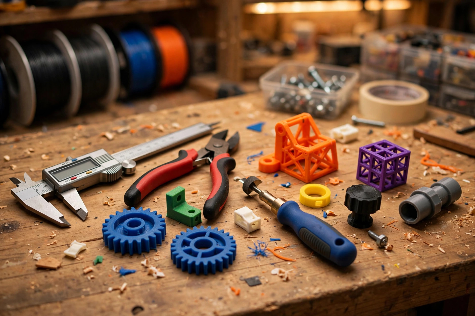
Random downloads can keep a new printer busy, but a deliberate first ten projects teaches more. The sequence below moves from first-layer observation to dimensional fit, bridging, supports, strength, and multi-part assembly. Choose simple models from a source you trust or design basic versions yourself. The goal is not a shelf of test objects; it is a set of skills you can reuse.
Before print one
Use a known-good spool of ordinary PLA and the printer's standard 0.20 mm profile. Clean the plate, complete calibration, confirm the nozzle size, and learn how to stop a print from the control panel. Keep a notebook or simple text file with material, profile, temperature, result, and one lesson. Do not change multiple settings between projects unless a safety or hardware issue requires it.
1. Single-layer square
Print a square only one layer high, roughly 60 mm across. This makes first-layer quality easy to inspect. Lines should touch and form an even sheet without gaps, ridges, or translucent scraping. Peel it off after cooling and flex it. If lines separate like strings, the nozzle was probably too far away or flow was inconsistent. This five-minute test is more useful than hiding a poor first layer beneath a large model.
2. Calibration cube
A small cube reveals corners, seam placement, top-surface closure, and rough dimensional accuracy. Measure it with calipers only after it cools. Do not immediately alter scale to correct a tiny difference; first confirm the calipers, filament flow, and whether the model includes intentionally raised letters. Use the cube to learn what normal walls and top infill look like.
3. Bed-wide set of five discs
Place a thin disc near each corner and one in the center. The set tests whether first-layer behavior stays consistent across the usable area. If only one region fails after cleaning, inspect plate seating and rerun the approved leveling routine. Do not compensate with a global nozzle offset that makes the good regions too close.
4. Overhang and bridge test
Choose a compact model with labeled overhang angles and short bridges. Watch how cooling and speed affect the underside. The steepest successful angle is not a universal machine score; it is a reference for this nozzle, material, profile, and room. Keep the result near the printer when deciding whether a future model needs support.
5. Cable clip
A simple clip introduces functional orientation and flex. Print one in the default orientation, test it gently, and inspect where the layer lines sit relative to bending. If it breaks along a layer, rotate the model or choose a more ductile material after mastering PLA. Measure the cable rather than trusting a generic label, because “USB cable” describes many diameters.
6. Small parts tray
A shallow tray teaches long perimeter consistency, corners, and bottom thickness while producing something useful. Use three walls and moderate infill. If a corner lifts, clean the plate and consider a brim before raising every temperature. Add rounded corners in CAD later and compare how geometry affects warping and handling.
7. Nut-and-bolt tolerance test
Print a purpose-designed tolerance sample or a simple threaded pair made for FDM. Test fits after cooling and remove any brim completely. This teaches that modeled dimensions, extrusion width, material shrinkage, and printer calibration all affect clearance. Record the smallest reliable gap rather than forcing a tight pair and declaring success.
8. Supported miniature object
Choose a small object with one obvious supported area, not a model buried in scaffolding. Enable supports from the build plate, use an interface if the profile provides one, and inspect the preview. After printing, wear eye protection and remove supports with controlled pressure. Compare the supported underside with a clean wall and note the gap setting.
9. Two-part box with fitted lid
A box and lid combine dimensional planning, flat surfaces, and assembly. Use a design with a clear stated tolerance or create a basic slip fit. Print a short corner section first if the full box is large. If the lid is loose or tight, adjust the clearance in the model rather than scaling the entire part, which also changes wall thickness and every other dimension.
10. Useful bracket for a light, noncritical load
Finish with a small wall-free bracket, under-desk hook, or holder that carries only a safe, light object. Measure the target, orient the part so layers follow the load path, use extra walls, and round inside corners. Test it gradually over a protected surface. Do not use an early print for overhead loads, electrical hardware, climbing, vehicle safety, or anything whose failure could injure someone.
How to learn from each result
Ask three questions after every print: Did the first layer look even? Did the model match the slicer preview? Did the finished part perform its intended job? Photograph one success and one flaw under similar light. A visible seam may be normal, while a split between layers is structural. Learn that distinction before chasing a perfectly smooth surface.
Change one thing on a reprint. If a bridge sagged, test cooling or bridge speed—not flow, temperature, acceleration, and retraction together. If a fitted lid is uniformly tight, modify clearance. If only one corner is tight, inspect warping or dimensional skew. Specific tests produce transferable knowledge.
What comes after the first ten
Reprint one project in PETG to compare flexibility and stringing. Design a replacement part with calipers. Try a larger nozzle for a strong utility object or a smaller layer height for visual detail while keeping the same nozzle. Build a small multi-part assembly with heat-set inserts only after practicing installation on scrap.
By print ten, you should understand the plate, recognize a healthy extrusion, navigate the slicer preview, choose basic orientation, and diagnose a few common flaws. That foundation is more valuable than a folder of mystery profiles. The next stage is not buying upgrades—it is applying those skills to a problem you genuinely want to solve.